|
|

|
|
Tuesday - March 12, 2002
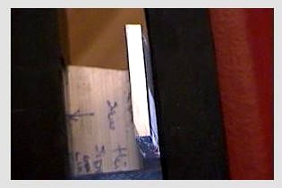
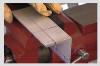
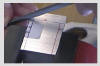
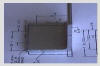
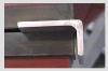
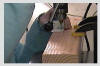
Back from mini-vacation and sawing on the aluminum angle. This is me working on my first part before I got the new hacksaw blade, tried all the tools and moved on to my second and third try. |
|
|
|
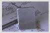
Tuesday - March 12, 2002
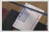
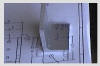
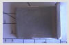
This is the first angle I worked on. Notice the pattern material. That worked great until I had to get close. |
|
|
|
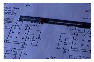
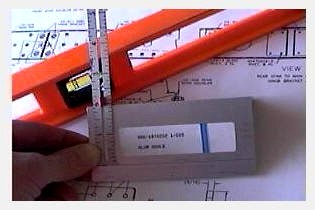
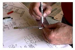
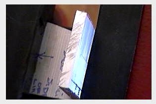
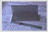
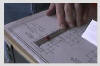
Sunday - March 17, 2002
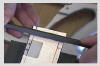
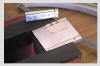
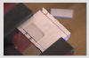
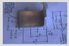
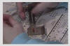
We have the new piece of angle in from Van's. Time to get started. This picture shows a 'poor-man's' micrometer. This handy device Jan pulled from her sewing kit. She did a great job measuring the the part on the plans and tranferring that to the angle. She keeps saying this is a lot like sewing. I believe! This also means that at least one of us has some experience! |
|
|
|
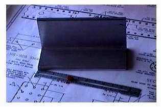
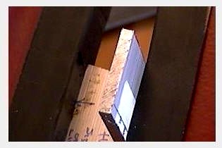
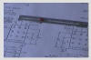
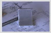
Sunday - March 17, 2002
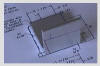
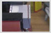
The angle, the sewing tool and the plans. |
|
|
|
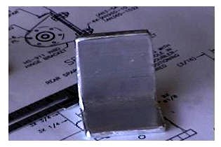
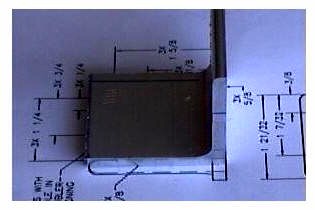
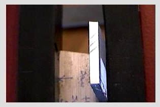
Sunday - March 17, 2002
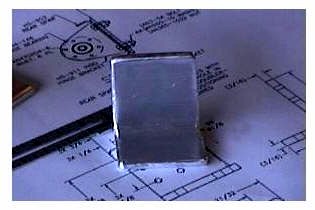
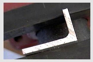
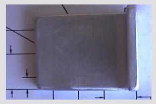
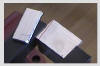
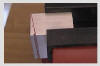
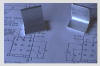
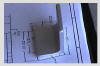
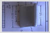
This is Jan's angle that she created. The second one that we did. My first one was a 'test'...yeah that's it a test. |
|
|
|
|
|
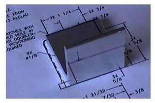
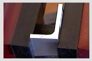
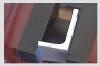
Sunday - March 17, 2002
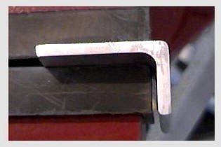
Another picture of her angle. We have yet to polish and round it. |
|
|
|
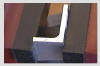
Sunday - March 17, 2002
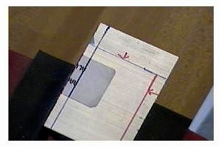
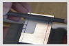
Laying out the lines with the sewing tool. |
|
|
|
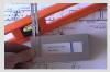
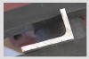
Sunday - March 17, 2002
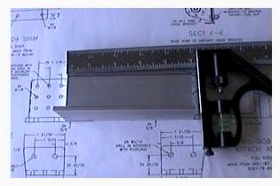
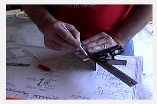
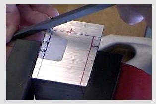
Laying out the long cut here line with a combination square. |
|
|
|
Sunday - March 17, 2002
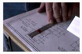
Measuring the part on the plans |
|
|
|
Sunday - March 17, 2002
marking the new measurement on the angle |
|
|
|
|
|
Sunday - March 17, 2002
More drawing of the cut lines |
|

|
|
Sunday - March 17, 2002
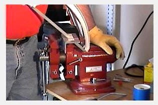
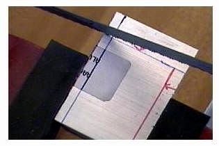
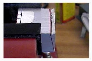
Starting to cut the angle. I noticed that it was difficult to accurately start the saw blad where I wanted it. |
|
|
|
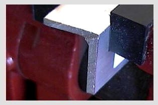
Sunday - March 17, 2002
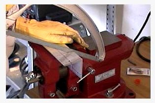
I thought I'd try cutting the angle this way. In the end it didn't work. It put too many hack saw marks on the part trying to go through two surfaces at the same time. By the time I got the marks cleaned up so the possibilty of stress fractures was eliminated the part was too small for my tastes. Oh well, that's why I got more angle..on to part number three. (NOTE: Only this step proved wrong). |
|
|
|
Sunday - March 17, 2002
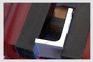
The angle in the bench vice with a couple of cuts. |
|
|
|
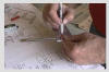
Sunday - March 17, 2002
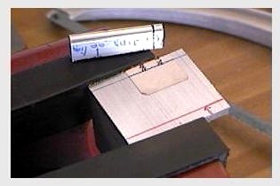
We discovered that it wasn't necessarily easy to start the hack saw blade without it slinding around on the metal part. I figured this procedure out to overcome that problem. I layed a triangular file parallel to my cut line with one of its surfaces flat on the metal. |
|
|
|

|
|
Sunday - March 17, 2002
Next I rotated the file so that one of the triangle points was facing down on the surface. Then I filed until I cut out a groove for the hacksaw blade to rest in when starting. See some later pictures to see the results of the file starting technique. |
|

|
|
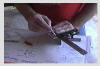
Sunday - March 17, 2002
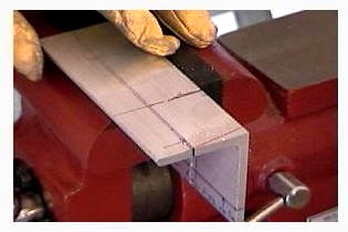
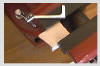
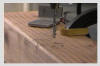
Cutting the foot off (the metal not mine). You can just make out the notch in the metal behind the saw blade. This is where the file was used to create a starting place for the saw. |
|
|
|
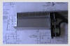
Sunday - March 17, 2002
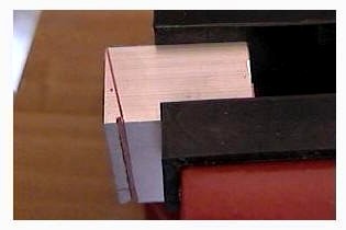
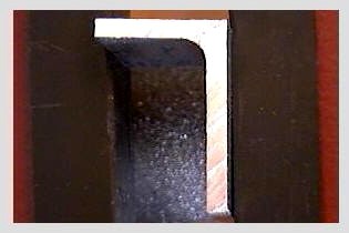
This shows how much metal is cut from the bottom of the angle to get to the proper size of the attach bracket. |
|
|
|
Sunday - March 17, 2002
This shows the file rotated so its ready to start creating the groove for the saw blade. |
|
|
|
Sunday - March 17, 2002
Starting the filing. Also note the cut lines. It's difficult to tell in this shot but the flat face of the file should be in line with the cut line so the back of the file forms a 90 degree angle with the metal. |
|
|
|

|
|
Sunday - March 17, 2002
This shows the groove that was created by the triangular file. You can also see the reason why the file is orientated in the manner described previously by looking at the results of the cut. |
|
|
|
Sunday - March 17, 2002
Starting the cut 'in the groove'. |
|
|
|
Sunday - March 17, 2002
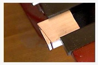
This shows the amount of metal cut off of the top of the attach bracket. |
|
|
|
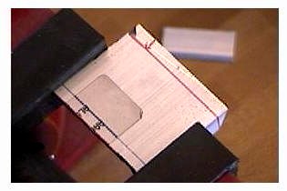
Sunday - March 17, 2002
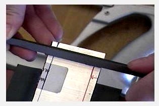
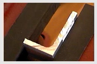
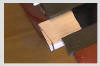
The cut piece laying on the plans for final verification of size. |
|

|
|
Sunday - March 17, 2002
Just a hair larger than the plans - perfect. Now on to polishing rounding, stress relief, etc. |
|
|
|
|
|
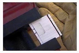
Sunday - March 17, 2002
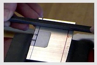
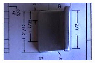
Laying on the plans from the side |
|
|
|
Sunday - March 17, 2002
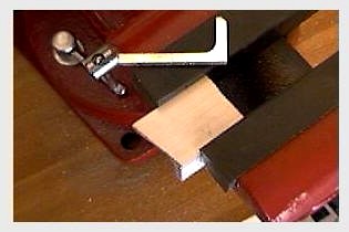
Checking the size of the foot. |
|
|
|
Sunday - March 17, 2002
Cutting the back edge on the side that the foot extends outward on |
|

|
|
Sunday - March 17, 2002
Not quite all the way through yet. Just enough to start the over edge and meet this cut at an angle. |
|
|
|
Sunday - March 17, 2002
Same cut with the bottom foot cut lines visible. You can see that the top cut doesn't go that far through the metal yet. |
|
|
|
|
|
Sunday - March 17, 2002
The bracket is flipped around ready to cut the angle of the foot. |
|
|
|
Sunday - March 17, 2002
You can see the results of the starter cut done with a file. This is right on line with the final cut line. |
|
|
|
Sunday - March 17, 2002
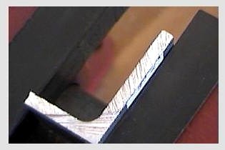
The foot side with the angle. This shows the meatl that had been cut away. |
|
|
|
Sunday - March 17, 2002
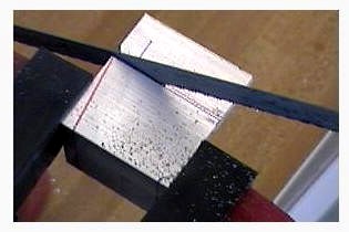
A close up of the rough surface left behind after the hacksaw cut. |
|

|
|
Sunday - March 17, 2002
This is the piece re-positioned after 4 passes with a fine grain file. |
|
|
|

|
|
Sunday - March 17, 2002
A few more passes and we're getting to a smoother surface. |
|
|
|
Sunday - March 17, 2002
Smoother still. You can see only one major hacksaw mark that needs to be smoothed out. |
|
|
|
Sunday - March 17, 2002
This angle shows the smoothing process even better. |
|

|
|
Sunday - March 17, 2002
Looks pretty good. It didn't take that much effort with the file to get here. |
|

|
|
Sunday - March 17, 2002
The top needs some smoothing work. |
|
|
|

|
|
Sunday - March 17, 2002
Again this only took about four passes with the file to get this result. |
|
|
|
Sunday - March 17, 2002
Just four more and we only have three scores left to work over. |
|

|
|
Sunday - March 17, 2002
This surface is done with the file. |
|
|
|
Sunday - March 17, 2002
Next surface up |
|

|
|
Sunday - March 17, 2002
First four file passes. |
|
|
|
|
|
Sunday - March 17, 2002
Done |
|
|
|
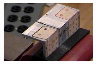
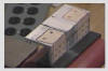
Sunday - March 17, 2002
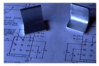
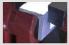
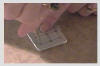
My piece on the left before final finish work and rounding off of the endges. Jan's completed piece on the right. |
|
|
|
Sunday - March 17, 2002
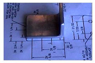
Finished - now how does the diminision compare to the plans? GREAT! |
|
|
|
Sunday - March 17, 2002
The foot diminision looks great too. |
|
|
|
Sunday - March 17, 2002
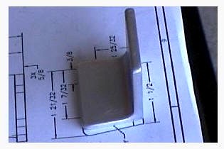
From the top. I can see that the piece in the plans isn't bigger than my 'fabricated' part. |
|
|
|
|
|
Sunday - March 17, 2002
Dead on - now time for the drill press! |
|
|
|
Tuesday - March 25, 2002
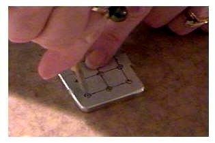
Jan marking the attach angles for the #30 holes that need to be drilled. |
|
|
|
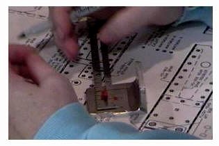
Tuesday - March 25, 2002
Jan using that great center punch tool she got for her birthday...hmmm...I wonder if she'll share? |
|
|
|
Tuesday - March 25, 2002
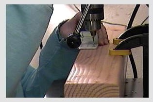
Jan drilling out her attach angle |
|
|
|
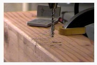
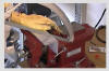
Tuesday - March 25, 2002
Could that be a hairy drill bit? Yes, it looks like it grew hairs from the dusting brush. Ok it must be time to call it a night! Maybe the drill bit will be bald in the morning. |
|
|


 This page will
attempt to document my learning experience in fabricating the Horizontal
Stabilizer Attach Angle Brackets (HS908-L & HS-908-R).
This page will
attempt to document my learning experience in fabricating the Horizontal
Stabilizer Attach Angle Brackets (HS908-L & HS-908-R).